(All In a Box)
VTETS-PVD3PSN
VTETS-PVD3PZN
(Panel Mounting ie with Cables & Switches)
Proportional Valve Driver, two PWM solenoid outputs, in sealed plastic enclosure.
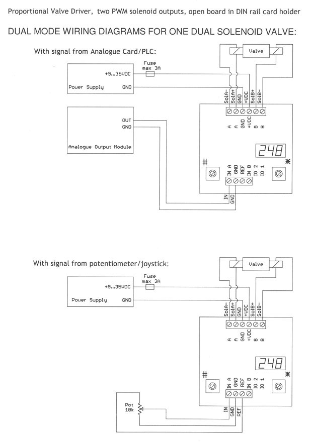
The Proportional Valve Driver is an electronic device powered by a regulated or unregulated DC supply or a battery (in mobile applications), it receives small power signals from a potentiometer, joystick, PLC, analogue output card, computer or other control device and delivers high power controlled current to the solenoid of a proportional valve in order to regulate through pressure or flow the motion of a hydraulic actuator.
Advantages Of Using Our Drivers
- Digital display confirms proper operation at a glance: it shows the input signal directly in Volts or mA, the output current directly in Amps or the driver settings names and values
- Only need one part number for input signals 0-5V, 0-10V, 0-20mA or 4-20mA, for coils rated 1A, 2A or 3A and power supply 12V or 24V
- The only tool you need to install and tune-up is a standard screwdriver
- Better linearity and control
- More effective dither
- Easy to read and duplicate settings
- Diagnosis possible even over the phone
- Insensitive to vibrations
- Wider operating voltage and temperature, output current, dither frequency range, independent up & down ramps
- Technical support by the designer, available 24/7 on request
Benefits And Features
- Versatile digital design
- Large, easy-to-use adjustments and three-digit seven-segment LED display
- Wide range of supply voltage
- Electronic limiting circuit / short circuit proof
- Load can be connected & disconnected live
- Protected against wrong connection
- Energy-efficient PWM circuit, no heat sink is required
- Current sensing maintains output regardless of changes in supply voltage and coil resistance
- Simple control with analog input, the reference voltage is locally supplied
- Can be used either for one dual solenoid valve or two independent single valves
- Plastic box with clear lid
- Three PG7 liquid-tight cable glands for power, signals and coils
Specifications
This product fulfills the essential requirements of the EMC Directive 2004/108/EC: EN61000-6-1:2005, EN61000-6-3:2006
- Operating voltage: 9 – 35VDC
- Maximum output current: 3A
- Ramp time: 0.0 to 99.5s
- Linearity: 0.5%
- PWM / Dither frequency: 50-500Hz
- Operating temperature: -40° to +75° Celsius
- Simple control with analog input, the reference voltage is locally supplied
- Can be used either for one dual solenoid valve or two independent single valves
- Plastic box with clear lid
- Three PG7 liquid-tight cable glands for power, signals and coils
- Input signals: user selectable 0-5V, 0-10V, 0-20mA or 4-20mA
- Size: 4.75” long x 2.25” deep x 3.15” wide (4.15” with cable glands)
Specifications
| AH1 | A high, output current corresponding to the highest input, 0.00 to 3.00 A |
| AJ9 | A jog, output current manual override, 0.00 to 3.00 A |
| ALO | A low, output current corresponding to the lowest input, 0.00 to 3.00 A |
| AUP | A ramp up, time required for the output to increase from ALO to AH1, 00.0 to 99.5 s |
| Adn | A ramp down, time req’d for the output to decrease from AH1 to ALO, 00.0 to 99.5 s |
| Adb | A deadband, output is disabled when signal is less than this setting, in % |
| Ain | Single mode A input signal, 005 (0-5V), 010 (0-10V), 020 (0-20mA) or 420 (4-20mA) |
| bH1 | B high, output current corresponding to the highest input, 0.00 to 3.00 A |
| bJ9 | B jog, output current manual override, 0.00 to 3.00 A |
| bLO | B low, output current corresponding to the lowest input, 0.00 to 3.00 A |
| bUP | B ramp up, time required for the output to increase from bLO to bH1, 00.0 to 99.5 s |
| bdn | B ramp down, time req’d for the output to decrease from bH1 to bLO, 00.0 to 99.5 s |
| bdb | B deadband, output is disabled when signal is less than this setting, in % |
| bin | Single mode B input signal: 005 (0-5V), 010 (0-10V), 020 (0-20mA) or 420 (4-20mA) |
| db | Dual mode deadband, output is disabled when signal is less than this setting, in % |
| dF | Dither frequency, 050 to 500 Hz in Dual mode input signal: 005 (0-5V), 010 (0-10V), 020 (0-20mA) or 420 (4-20mA) |
| di | Display orientation, normal or up-side-down |
| SA | Save settings |
Set-Up Procedure
At power up, you may rotate the left side control to select the variable, displayed: Ain (A input), Aot (A output), bin (B input) or bot (B output), the actual solenoid output current directly in Amps or the command input signal in V or mA, corresponding to the input range pre-selected. To enter setup mode, rotate right side control ; the display will show the settings sequentially: AH1, AJ9, ALO, AUP, Adn, Adb, Ain, bH1, bJ9, bLO, bUP, bdn, bdb, bin, db, dF, in, di and SA.
When you reach the setting that you want to modify, rotate up or down to the desired value. To modify another setting, rotate and repeat. The Driver is fully functional during the set-up procedure with any adjustments effective immediately (except the input range selection that becomes effective only after saving). In order to write the new settings in the memory and return to normal mode of operation, rotate until the display shows SA and then rotate one full turn. If you do not want to keep the new settings, simply power down without saving.